
Surge protection in the distribution board: T1, T2, T3 and the earthing system
Overvoltage reaches a board from a nearby or line lightning strike and from switching in the network. It lasts microseconds but can damage boiler controls, a heat pump, a router or a TV. A surge protective device (SPD, "surge arrester") diverts this impulse to earth. This guide explains how to choose the SPD type and scheme and what to check in the specification.
This article is not a connection guide. An SPD is installed by an electrician according to the design and the manufacturer's instructions.
What LBN 261-15 says
- Point 25.4: protection against lightning current and overvoltage is one of the protective functions by which protective devices are chosen.
- Point 44: lightning protection is mandatory in third-group buildings. In other cases the need is determined by building characteristics and risk criteria per LVS EN 62305-2.
- Point 47: dwellings (and several other building types) are provided with at least a class III lightning protection system.
- The term "lightning protection system" in the code (point 2.3) includes external and internal lightning protection as well as surge protective devices.
For overvoltage protection in installations, the LVS standards list includes LVS HD 60364-4-443:2016. How these requirements apply to a specific building and whether external lightning protection is needed is assessed by the designer. Here we only cover the SPD in the board.
T1, T2, T3: where each goes
| Type | Tested with | Where used (manufacturer guidance) |
|---|---|---|
| T1 (class I) | Lightning impulse current Iimp (10/350 µs) | At the origin when the building has external lightning protection or an overhead supply and the designer requires it |
| T2 (class II) | Nominal discharge current In (8/20 µs) | In the main board — the most common solution for a house without external lightning protection; also in sub-boards |
| T3 (class III) | Combination wave | Near sensitive equipment, as an extra stage after T2 |
ABB and Weidmüller guidance: T1 is needed when the building has external lightning protection or is fed by an overhead line. If the building has no external lightning protection and is fed by cable, T2 in the main board is usually sufficient. The decision is the designer's.
The range currently has T2 devices. T1 and combined T1+T2 devices are in preparation.
Scheme by earthing system
The SPD must match the earthing system at the board's location. In Latvia the supply is often TN-C, split into TN-C-S in the building. Private houses with their own earth electrode may also be TT. Exactly where the PEN is split is set by the design and the operator's technical conditions.
| System at the board | Scheme | Example |
|---|---|---|
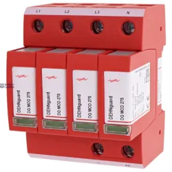
| TN-C (PEN not yet split) | 3+0: L1, L2, L3 to PEN | Dehn DG M TNC 275 (952300) |
| TN-S / TN-C-S after the split | 4+0: L1, L2, L3, N to PE | Dehn DG M TNS 275 (952400) |
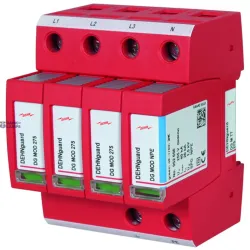
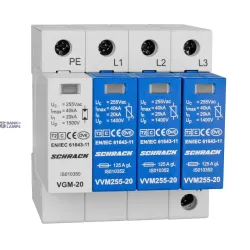
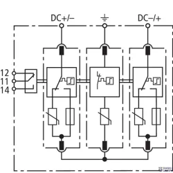
| TT or TN-S | 3+1: L to N plus an N–PE spark gap stage | Dehn DG M TT 275 (952310), with FM remote signalling (952315), Schrack 3+1 set |
The 3+1 scheme is intended for TT systems and can also be used in TN-S. Manufacturers recommend it when the SPD must sit upstream of residual current protection. If the SPD is downstream of an RCD, manufacturers recommend a type S or high-immunity RCD so that discharging an impulse does not cause tripping.
All Dehn models listed are three-phase devices. A single-phase supply needs a different configuration (e.g. 1+1), which is not currently in the range.
Parameters to compare
| Parameter | Meaning | Dehn DG M TT 275 FM (datasheet) |
|---|---|---|
| Uc | Maximum continuous operating voltage | 275 V (L–N), 255 V (N–PE) |
| In / Imax | Nominal / maximum discharge current 8/20 µs | 20 kA / 40 kA |
| Up | Voltage protection level — lower is better | ≤ 1.5 kV |
| Max backup protection | Largest fuse upstream of the device | 125 A gG |
| Remote signalling | Contact for a fault signal | Yes (FM version) |
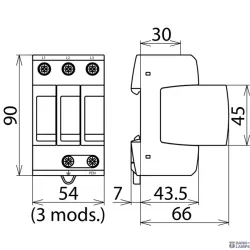
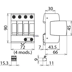
| Width | Board space | 4 modules |
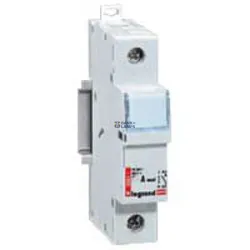
If the upstream protection is larger than the maximum backup protection in the datasheet, a separate fuse or circuit breaker is provided in the SPD circuit. Its rating comes from the SPD manufacturer's table. Example of a fuse holder: Legrand 10×38 holder; see the full range in the fuses category.
Installation principles from manufacturer guidance
- Short connection: the Schneider Electrical Installation Guide recommends a total SPD connection lead length of no more than 50 cm. A longer lead increases the voltage that reaches equipment.
- Cross-section: per the manufacturer's instructions. The same guide gives a minimum of 4 mm² Cu for T2 and 16 mm² Cu for T1 devices.
- Status indicator: on DEHNguard modules green means operational, red means the module must be replaced. Check after a thunderstorm.
- Location: as close to the origin as possible, ahead of sensitive equipment.
Solar panels
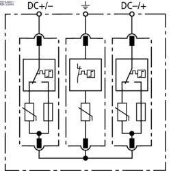
Dehn 952510 and Dehn 952515 (DEHNguard M multipole, T2) are intended for the DC side of solar installations up to 1000 V DC. They are not intended for an AC board. DC-side protection is chosen per the inverter and panel manufacturers' requirements.
Common mistakes
- The scheme does not match the earthing system.
- Long, looped connection leads that reduce protection.
- Maximum backup protection ignored.
- Believing a T2 device replaces external lightning protection — it does not.
- Nobody checks the status indicator, and the device sits failed for years.
Sources and date checked
- LBN 261-15, points 2.3, 25, 44–47. Checked on likumi.lv on 18 October 2026.
- LVS list of applicable standards (in force from 09.01.2026) — LVS HD 60364-4-443:2016.
- Schneider Electric Electrical Installation Guide — SPD, connection, backup protection; ABB and Weidmüller surge protection guidance.
- Dehn DEHNguard M datasheets (952300, 952310, 952315, 952400).
Where the SPD fits in the board specification: distribution board bill of materials. All devices — in the circuit breakers and RCDs category.
Related products
Reviews
Be the first to review this article.
Write a review